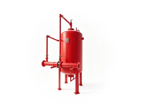
Vertical Foam Bladder Tank

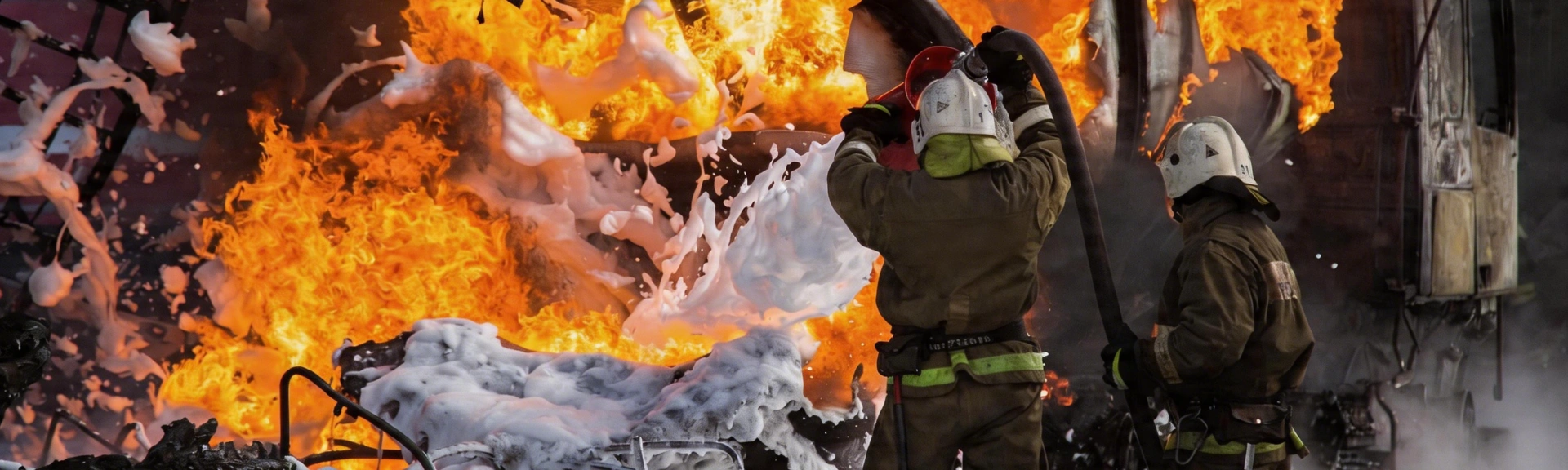
Foam bladder tanks are ideal for municipal, commercial, and industrial facilities requiring reliable fire protection. They are easy to install and maintain, with flexible configurations for projects of all sizes.
Delivering fast and effective suppression, the foam smothers flames and prevents fire spread—providing a reliable and efficient solution for high-level fire protection.
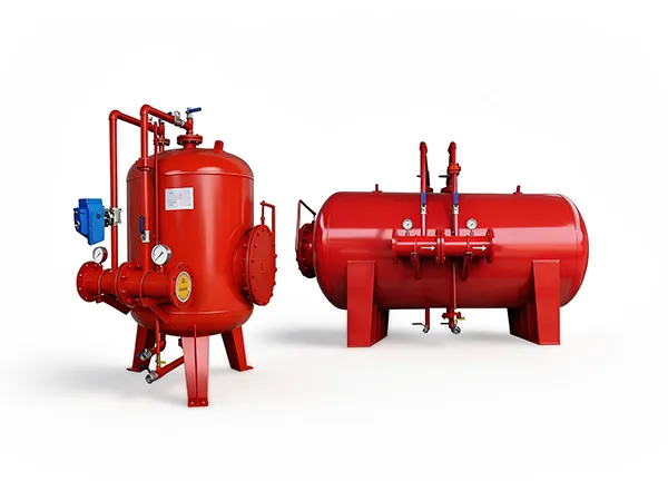
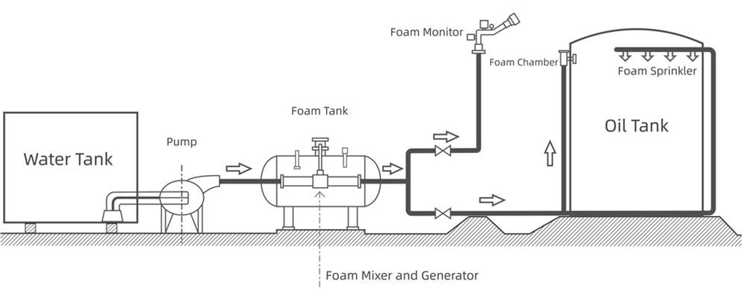
A foam bladder tank is a steel pressure vessel with an internal bladder used to store foam concentrate. When pressurized water flows through the system, a proportioner diverts a portion of the water flow into the annular space of the tank, compressing the bladder and displacing the foam concentrate. The concentrate is then metered and mixed with water in the proportioner to form a foam solution at the required ratio. The foam solution is delivered through piping to foam discharge devices for direct application to the protected hazard for fire suppression.
Vertical Foam Bladder Tank
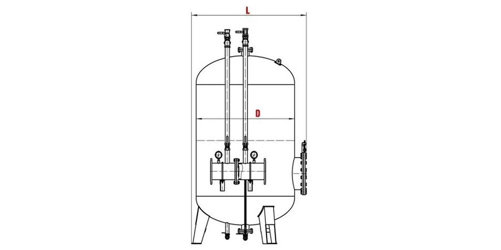
Schematic Diagram
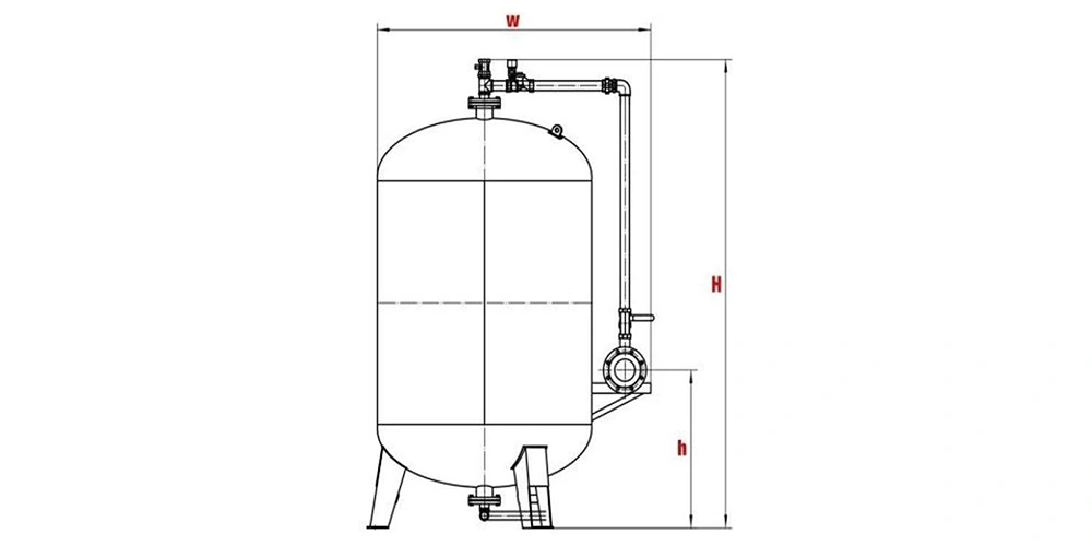
Schematic Diagram
| Capacity | L (mm) | W (mm) | H (mm) | H (mm) | D (mm) |
|---|---|---|---|---|---|
| 1000 L | 1955 | 1250 | 1540 | 930 | 910 |
| 1500 L | 2230 | 1350 | 1640 | 930 | 1010 |
| 2000 L | 2485 | 1450 | 1740 | 930 | 1112 |
| 2500 L | 3010 | 1450 | 1740 | 930 | 1112 |
| 3000 L | 3040 | 1610 | 1880 | 960 | 1216 |
| 4000 L | 3430 | 1710 | 1980 | 960 | 1316 |
| 5000 L | 3670 | 1810 | 2080 | 960 | 1420 |
| 6000 L | 3830 | 1910 | 2180 | 960 | 1520 |
| 7000 L | 3935 | 2010 | 2280 | 960 | 1620 |
| 8000 L | 4300 | 2010 | 2280 | 960 | 1620 |
| 10000 L | 4625 | 2220 | 2480 | 960 | 4625 |
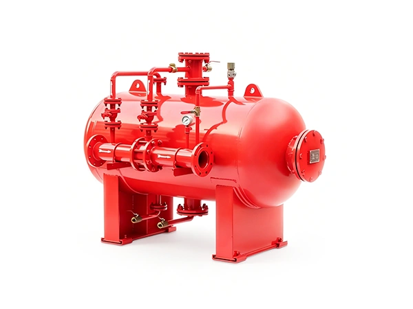
Horizontal Foam Bladder Tank
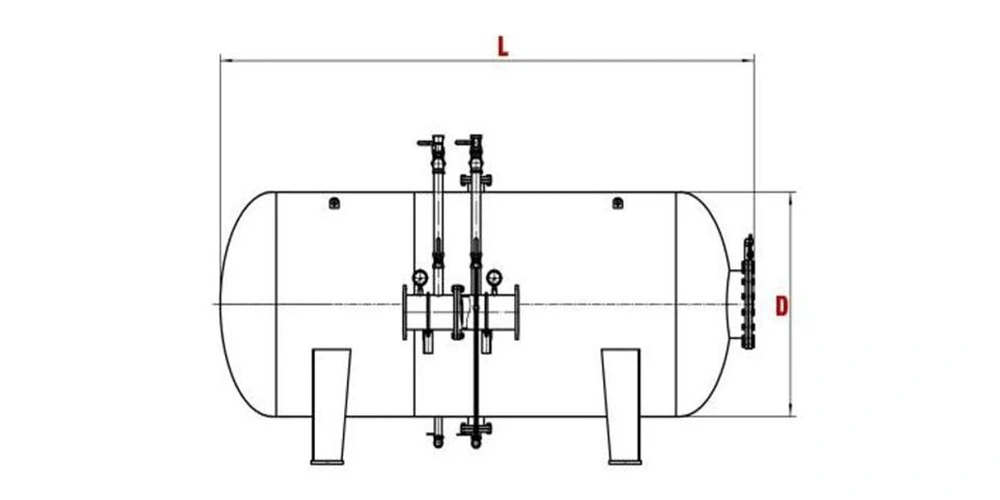
Schematic Diagram
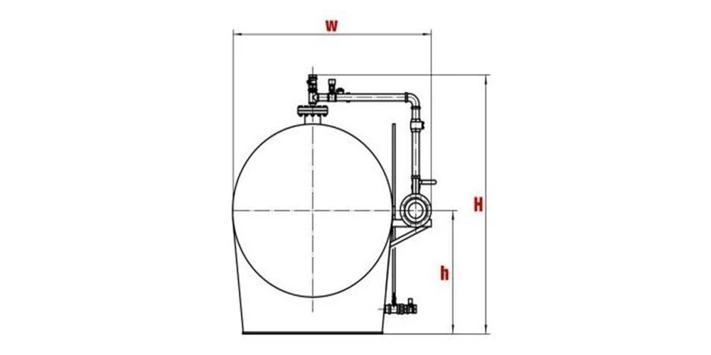
Schematic Diagram
| Capacity | L (mm) | W (mm) | H (mm) | H (mm) | D (mm) |
|---|---|---|---|---|---|
| 500 L | 920 | 1145 | 1820 | 860 | 810 |
| 1000 L | 1190 | 1345 | 2100 | 890 | 1010 |
| 1500 L | 1290 | 1440 | 2410 | 900 | 1105 |
| 2000 L | 1400 | 1545 | 2610 | 900 | 1212 |
| 2500 L | 1525 | 1647 | 2720 | 915 | 1312 |
| 3000 L | 1620 | 1805 | 2855 | 930 | 1416 |
| 4000 L | 1830 | 2010 | 2875 | 970 | 1616 |
Carefully selected fire protection products to meet the needs of engineering projects.